
R68R
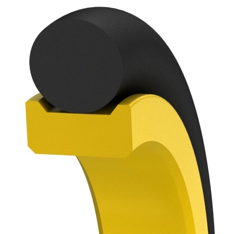
Small cross-section low-friction internal swivel seal
Composite seal for sealing rod of swivel joints and rotary couplings.
This seal is designed to retrofit O-ring glands, to minimize system friction, and to provide a positive seal on the rod. It is used where radial grooves must be kept as small as possible. Up to 3,500*psi. Small quantities are available in 1 to 3 days.
Operating Range
| Material | Max.Pressure | Temperature | Surface Speed | Application | Dry-run | PV-Rating |
|---|---|---|---|---|---|---|
| Permachem 6233 | 3,500psi (240bar) | -58 to 400°F (-50 to 200°C) | Up to 400 fpm (2m/s) | standard oil lubrication, high waterbased fluids | YES | 7 |
| Permachem 6235 | 3,500psi (240bar) | -58 to 400°F (-50 to 200°C) | Up to 400 fpm (2m/s) | Soft shaft material, gaseous media, FDA compliant | YES | 7 |
| Duraloy 4736 | 3,500psi (240bar) | -58 to 400°F (-50 to 200°C) | Up to 400 fpm (2m/s) | low wear and abrasion, long service life | YES | 7 |
Size Table (Inch)Standard sizes listed below are preferred sizes for new design applications; however, we offer any other seal size as required.Seals are available for any shaft diameter size in 0.001 inch increments without tooling charges, including Functional Range.
| A Shaft Diameter | CS Cross-section | D Bore Diameter | B Diameter | Tolerance | L designed for no back-up ring groove | L designed for 1back-up ring groove | L designed for 2 back- up rings groove | C | R1 Radius | R Radius |
||
|---|---|---|---|---|---|---|---|---|---|---|---|---|
| Standard Range | Functional Range | Tolerance | * | D= | B= | D, B | Tolerances +0.005/-0 | min. | max. | max. | ||
| 0.120-0.499" | 0.120 - 3.000" | +0/-0.0015 | 0.065 | A + 0.130 | A + 0.002 | +0.001/-0 | 0.090 | 0.140 | 0.205 | 0.040 | 0.005 | 0.005 |
| 0.500-0.999" | 0.200 - 4.000" | +0/-0.002 | 0.098 | A + 0.196 | A + 0.002 | +0.002/-0 | 0.140 | 0.170 | 0.240 | 0.060 | 0.010 | 0.005 |
| 1.000 - 1.499" | 0.750 - 6.000" | +0/-0.0025 | 0.139 | A + 0.278 | A + 0.003 | +0.002/-0 | 0.190 | 0.210 | 0.275 | 0.080 | 0.020 | 0.005 |
| 1.500 - 4.999" | 1.500 - 10.000" | +0/-0.0035 | 0.203 | A + 0.406 | A + 0.004 | +0.003/-0 | 0.280 | 0.310 | 0.410 | 0.090 | 0.025 | 0.005 |
| 5.000 - 25.999" | 4.500 - 26.000" | +0/-0.005 | 0.287 | A + 0.574 | A + 0.005 | +0.004/-0 | 0.380 | 0.410 | 0.540 | 0.130 | 0.035 | 0.005 |
| ≥26.000" | consult AHPSeals engineering | |||||||||||
| *Standard cross-sections (CS) listed and non-standard sizes can be provided for any shaft size up to 63 inches. Surface finish: Shaft (A) plunge ground, zero lead, Ra 8-16µin using elastomer seals, Ra 6-12µin using PTFE seals. Housing (D,L) Ra 32-63µin, shaft material hardness 55-65RC. See Technical Info for more specific information. | ||||||||||||
Seal Housing Drawing
