
SB10HPR
Extreme temperature high-pressure single-lip PTFE rotary shaft seal
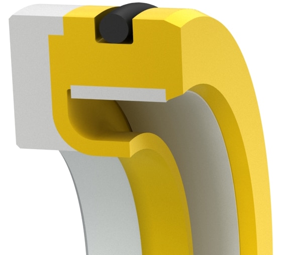
This seal design incorporates an anti-extrusion and support ring geometrically matched to the primary seal lip. This seal is capable of handling higher pressures, extreme temperatures, aggressive media, high surface speeds, and can even run dry. A metallic thermal control ring provides dimensional control under thermal cycling conditions. An integrated O-ring on the OD of the seal serves as an anti-rotation device and maximizes static sealing between the seal and the bore. Small quantities are available in 2-4 days.
Operating Range
| Material | Continuous Pressure | Max.Pressure Spike | Temperature | Surface Speed | Application | Dry-run | PV-Rating |
|---|---|---|---|---|---|---|---|
| Permachem 6233 | 500psi (35bar) | 750psi (50bar) | -58 to 400°F (-50 to 200°C) | Up to 3,500 fpm (17.5m/s) | standard oil lubrication, high waterbased fluids | YES | 10 |
| Permachem 6235 | 500psi (35bar) | 750psi (50bar) | -58 to 400°F (-50 to 200°C) | Up to 3,500 fpm (17.5m/s) | Soft shaft material, gaseous media, FDA compliant | YES | 10 |
| Duraloy 4736 | 500psi (35bar) | 750psi (50bar) | -58 to 400°F (-50 to 200°C) | Up to 3,500 fpm (17.5m/s) | low wear and abrasion, long service life | YES | 10 |
Size Table (Inch)Standard sizes listed below are preferred sizes for new design applications; however, we offer any other seal size as required. Seals are available for any shaft diameter size in 0.001 inch increments, including Functional Range.
| A Shaft Diameter | CS Cross-section | D Bore Diameter | B without wiper lip +/- 0.010 | B with wiper lip +/- 0.010 | L | F | C | R |
|||
|---|---|---|---|---|---|---|---|---|---|---|---|
| Standard Range | Functional Range | Tolerance | * | D= | Tolerance | B= | B= | +0.012/-0 | +/-0.010 | min. | max. |
| 0.315 - 0.999" | 0.315 - 5.000" | +/-0.003 | 1/4 | A + 0.500 | +/-.001 | A + 0.030 | A + 0.120 | 0.325 | 0.265 | 0.070 | 0.020 |
| 1.000 - 5.999" | 0.315 - 18.000" | +/-0.003 | 3/8 | A + 0.750 | +/-.001 | A + 0.030 | A + 0.120 | 0.325 | 0.265 | 0.085 | 0.020 |
| 6.000 - 15.999" | 0.500 - 26.000" | +/-0.004 | 1/2 | A + 1.000 | +/-.002 | A + 0.035 | A + 0.120 | 0.375 | 0.310 | 0.090 | 0.030 |
| 16.000 - 25.999" | 0.500 - 26.000" | +/-0.006 | 5/8 | A + 1.250 | +/-.003 | A + 0.040 | A + 0.120 | 0.512 | 0.425 | 0.100 | 0.030 |
| 26.000 - 63.000" | consult with Ahpseals engineering | ||||||||||
| *Standard cross-sections (CS) listed and non-standard sizes can be provided for any shaft size up to 63 inches.Surface finish: Shaft (A) plunge ground, zero lead Ra 6-12µin - Housing (D,L) Ra max. 32µin - Shaft material hardness 55-65RC. Use of installation tool is highly recommended. See Technical Info for more specific information. | |||||||||||
Seal Housing Drawing
